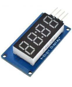

TM1637 4 Bits Digital Tube LED Display Module With Clock Display for Arduino
₹49.00 (incl. GST)
In stock
Additional Information
✅ Free Shipping on Orders Above ₹999
✅ Items on Website is Ready Stock at our Store for Immediate Shipping
✅ Secure Checkout | Trusted Payments
✅ Estimated Delivery?
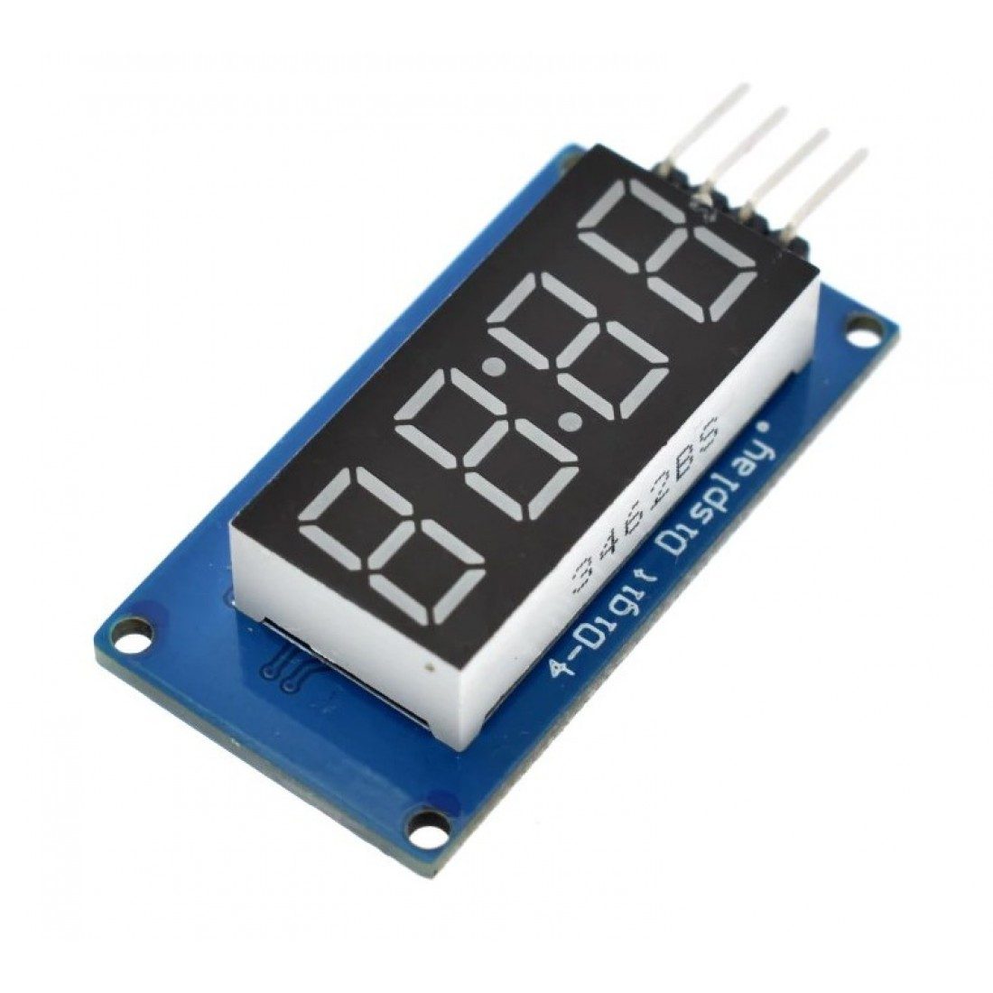
TM1637 4 Bits Digital Tube LED Display Module is a 12-foot clock with 4 points of positive digital (0.36 inches) display module driver tm1637 ic, only two signal lines can make SCM four 8-segment LED.
TM1637 DISPLAY is preferred module that can be interfaced to any system using only two pins. This is the main reason the module is preferred over other module. The characters to be displayed on the screen can be sent to module using only two pins. With that we can save many I/O pins of system which can be used for other important tasks.
Another main reason TM1637 display is preferred is because of its low cost. Although there are other display modules present in the market they cost more. The module design is robust so it can sustain in tough environments and still can perform its function for a long time. The module consumes low power and can be installed in mobile applications.
Features:
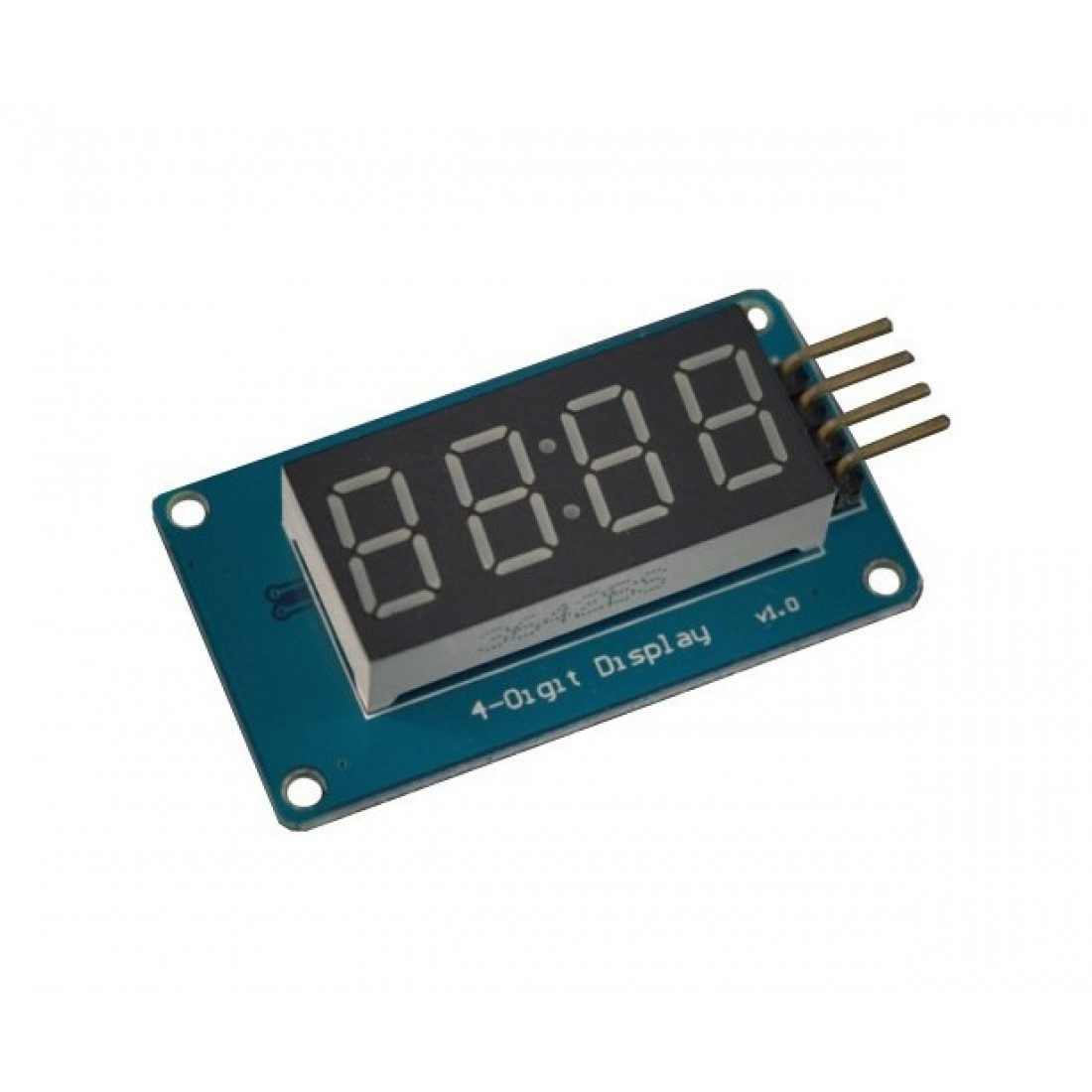
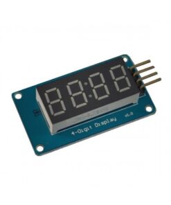
- Display device is 4-digit yang red digital tube
- Digital tube 8-level grayscale adjustable
- Control interface level can be 5V or 3.3V
- 4 M2 screw positioning holes for easy installation
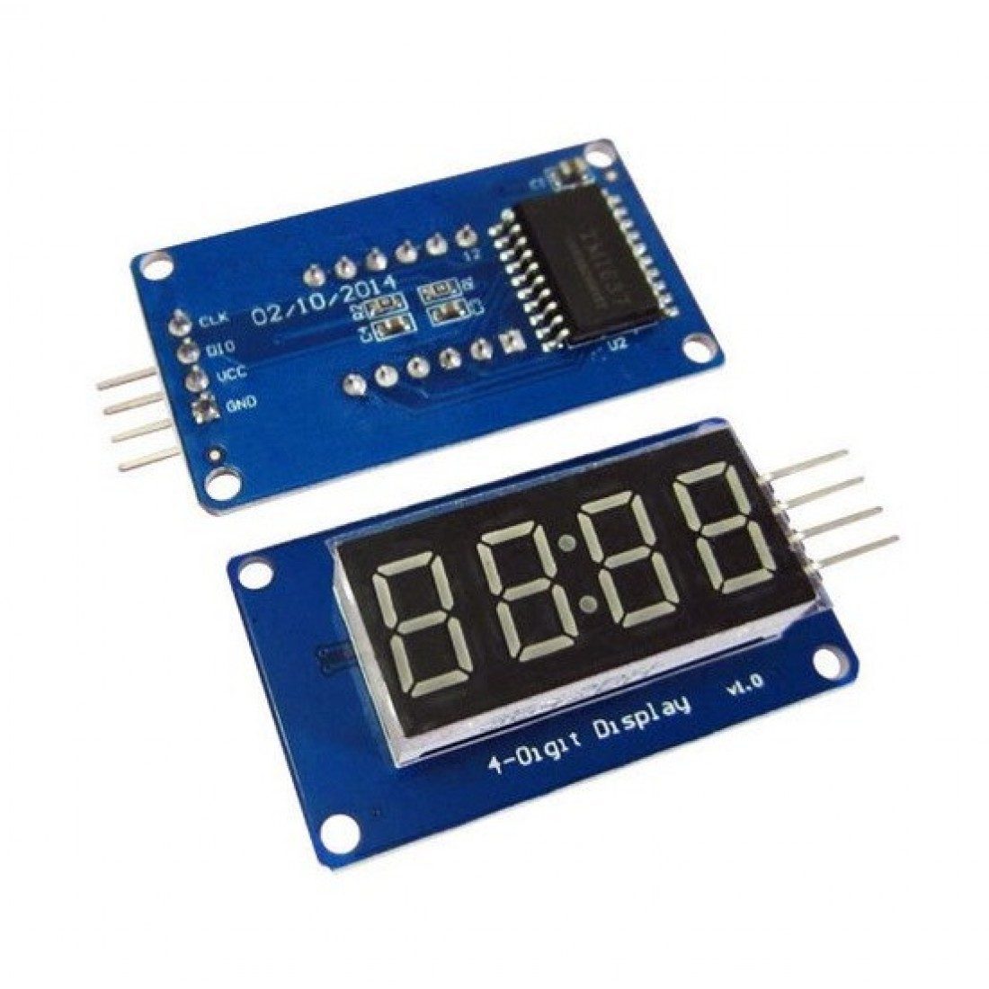
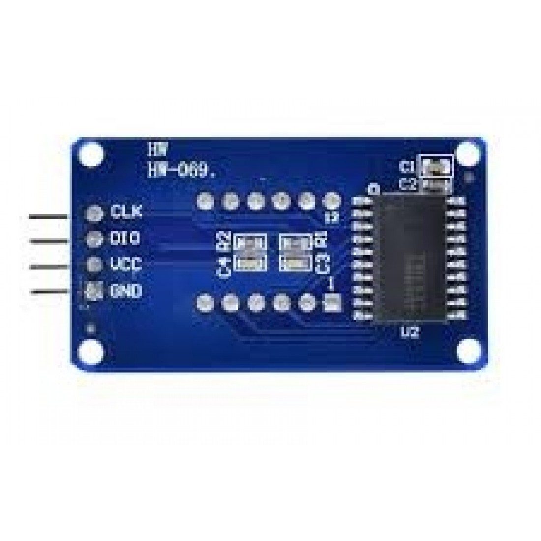
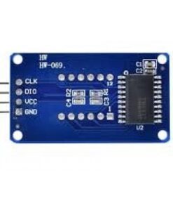
- Control interface A total of 4 pins (GND, VCC, DIO, CLK), GND is ground, VCC is the power supply, DIO is the data input and output pin, CLK is the clock signal pin;
- Digital Tube: 4-digit common anode with a 0.36-inch digital tube with a score point, highlighted in red;
- Positioning hole: 4 M2 screw positioning holes, the hole diameter is 2.2 mm, which makes the module easy to install and position, and realize the module combination;
Specifications:
- Input Voltage (V):3.3 to 5.5
- Max. Operating Current (mA):30
- Length (mm):42
- Width (mm):24
- Height (mm):12
- Weight (g):10
Pinout Description:
- GND – GND
- Vcc – 5V
- DIO – D2
- CLK – D3
Package Includes:
- 1 x 4 Bits Digital Tube LED Display Module.
1 review for TM1637 4 Bits Digital Tube LED Display Module With Clock Display for Arduino
Add a review
Related products


Bhagwan Sahay Kumawat –
Thanks sir mujhe parcel mil Gaya hai saman ki quantity bhi okay hai