-
×
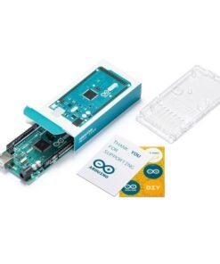
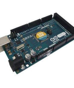
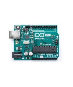 Original Arduino Uno Rev3 A000066
₹1,919.00
Original Arduino Uno Rev3 A000066
₹1,919.00

 2")

DIY 5kg Precision Jewelry Electronic Scale Kit is the electronic scale to calculate the magnitude of the force based on the weak deformation of the metal after the force is applied, which can be regarded as the content that will be exposed in the first experimental class of “Materials Mechanics”. Strain gauges are the most commonly used to measure the weak deformation of metals. In a typical application, strain gauges attached to the material surface in different orientations and angles can measure the current tensile, bending and torsion forces on the material.
Of course, making an open source electronic scale is not so complicated. On the one hand, it has a weighing module, and on the other hand, it also has a weighing-specific AD chip (hx711), plus Arduino and the corresponding library library, which is very simple.
Because the output and weight of the AD module have a linear relationship within the module range, it is basically a problem of adjusting the scale factor and offset. The measured values are also averaged in the class library to make the output more stable. A 3kg module can basically achieve an accuracy of +/- 0.2g, which is sufficient for general applications. The application of the weighing module is not limited to this. It is no problem to use it to measure the percussion force.
HX711 module technical parameters:
HX711 is a 24-bit A/D converter chip specially designed for high-precision load cells. Compared with other chips of the same type, this chip integrates peripheral circuits required by other chips of the same type, including regulated power supply, on-chip clock oscillator, etc. It has the advantages of high integration, fast response speed, and strong anti-interference. The overall cost of the electronic scale is reduced, and the performance and reliability of the overall machine are improved. The interface and programming between the chip and the back-end MCU chip are very simple, all control signals are driven by pins, and there is no need to program the internal registers of the chip. The input selection switch can select channel A or channel B arbitrarily, which is connected to its internal low-noise programmable amplifier. The programmable gain of channel A is 128 or 64, and the corresponding full-rated differential input signal amplitude is ±20mV or ±40mV, respectively. Channel B is a fixed gain of 32, which is used for system parameter detection. The regulated power supply provided in the chip can directly provide power to external sensors and the A/D converter in the chip, and no additional analog power supply is required on the system board. The clock oscillator in the chip does not require any external devices. The power-on automatic reset function simplifies the initialization process of power-on.
Features:
- Two selectable differential inputs
- On-chip low-noise programmable amplifier with selectable gains of 64 and 128
- On-chip voltage regulator circuit can directly provide power to external sensors and on-chip A/D converters
- The on-chip clock oscillator does not require any external devices, and an external crystal or clock can also be used if necessary
- Power-on automatic reset circuit
- Simple digital control and serial communication: all controls are input by pins, and the on-chip registers do not need to be programmed
- Selectable output data rate of 10Hz or 80Hz
Debugging of Arduino electronic scale
Wiring Diagram:
- VCC can be any value in 2.6-5.5, because we are using Arduino, so it is directly powered by 5V and GND is grounded.
- SCK is connected to Pin 9 of Arduino and DT is connected to Pin10. These two pins can be changed in the program.
- E+, E-, A+ and A- are respectively connected to the bridge sensor: the excitation voltage is positive and negative, and the output voltage is positive and negative
- (E+ is connected to the red wire; E- is connected to the black wire; A+ is connected to the green or blue wire; A- is connected to the white wire).
- B+ and B- are connected to the sensor of channel B, and can also be connected to the power supply through a voltage divider circuit to detect the power supply voltage. It’s best to connect to GND if you don’t use it, but it doesn’t matter if I try to connect it.
Sample Program :
#include <HX711.h> // include the header file of the library
HX711 hx(9, 10); // Data pin definition
void setup() {
Serial.begin(9600);
}
void loop()
{
Double sum = 0; // In order to reduce the error, take out 10 values at a time and calculate the average value.
For (int i = 0; i <10; i++) // The more loops, the higher the accuracy, and of course the more time it takes
Sum += hx.read(); // accumulate
Serial.println(sum/10); // Find the average value for the average difference
}
The sample program given is very simple, but I check that there are many functions in the library that are not given in the example:
- HX711(byte sck, byte dout, byte amp = 128, double co = 1); // Define sck and dout pins, gain Multiple (default 128) and correction factor (default 1)
- void set_amp(byte amp); // Change the gain multiple and the corresponding channel, and it will work after calling read() at least once
- bool is_ready(); // Returns whether hx711 is available, it will be called in the read() function
- long read(); // Returns the sensor voltage value, if hx711 is not available, the program will pause in this function
- double bias_read(); // Return: (read()-offset value) * correction factor
- void tare(int t = 10); // Add the tare weight to the offset value, affecting each read(); call
- void set_co(double co = 1); // Modify the correction coefficient (default is 1)
- void set_offset(long offset = 0); // Modify the offset value (default is 0). It can be seen that HX711 can also be defined in a four-parameter way, and at the same time specify the gain multiple and correction coefficient. In the program running, you can also change the gain multiple, correct the coefficient and use the offset value to realize the functions of tare removal at any time, which is very practical.
- The only thing that needs to be explained here is the first function, HX711 hx(9, 10); // In this way, only the SCK and DOUT pins are defined. AMP uses the 128-bit gain of channel A by default, and the correction coefficient defaults to 1;
- HX711 hx(9, 10, 64); //In this way, define the SCK and DOUT pins with instructions. AMP uses the 64 gain of channel A, and the correction coefficient is 1 by default;
- HX711 hx(9, 10, 32, 1.4); //Define the SCK and DOUT pins in this way, AMP uses the 32-bit gain of channel B, and the correction factor is 1.4;
Regarding the choice of channels and gain multiples, as mentioned in the information, channel A has only two gain multiples of 128 and 64 bits, corresponding to full-load voltages of 20mV and 40mV, channel B has only fixed 32-bit gain multiples, and full-load voltage is 80mV , When using, the input voltage of each channel should not exceed the full load voltage of the corresponding gain multiple. Of course, the program can be switched at any time.
Package Includes:
- 1 x HX711 weight sensor module
- 1 x 5kg weight sensor
- 1 x 1602 iic module
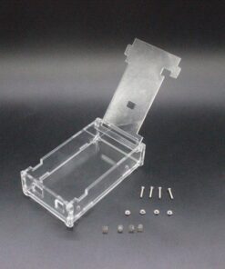
- 1 x mini acrylic stand+screw
- 1 x uno R3
- 1 x Dupont cables
Only logged in customers who have purchased this product may leave a review.
Related products
₹1,650.00 (incl. GST)
₹69.00 (incl. GST)
₹138.00 (incl. GST)
₹135.00 (incl. GST)
₹47.00 (incl. GST)
₹160.00 (incl. GST)
₹82.00 (incl. GST)
₹3,375.00 (incl. GST)
Reviews
There are no reviews yet.